/ 2
/ 2
AD-365
3-Way with a dish, a dome, and a ribbon
| Type | Three-Way |
| Impedance | 4 Ω |
| Power | 60 W |
| Drivers | 2 (2 bands) |
| Low end | 40 Hz |
| Build cost | ≈ $275.00 |
| Published | 29 Oct 2026 |
Measured response
About this design
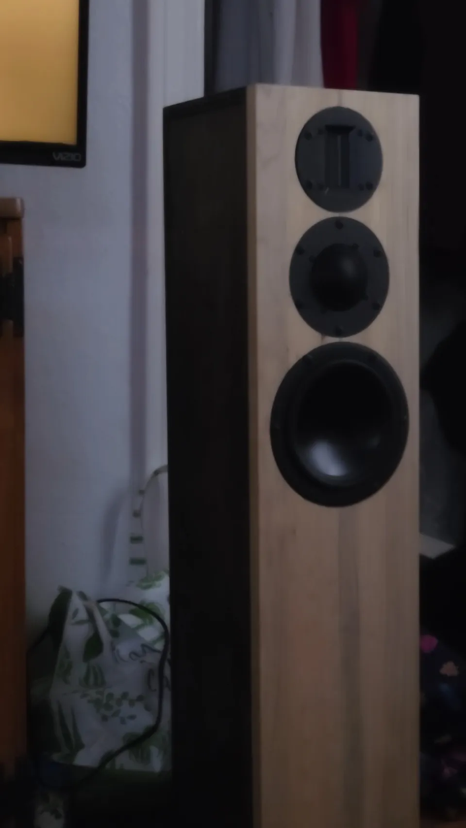
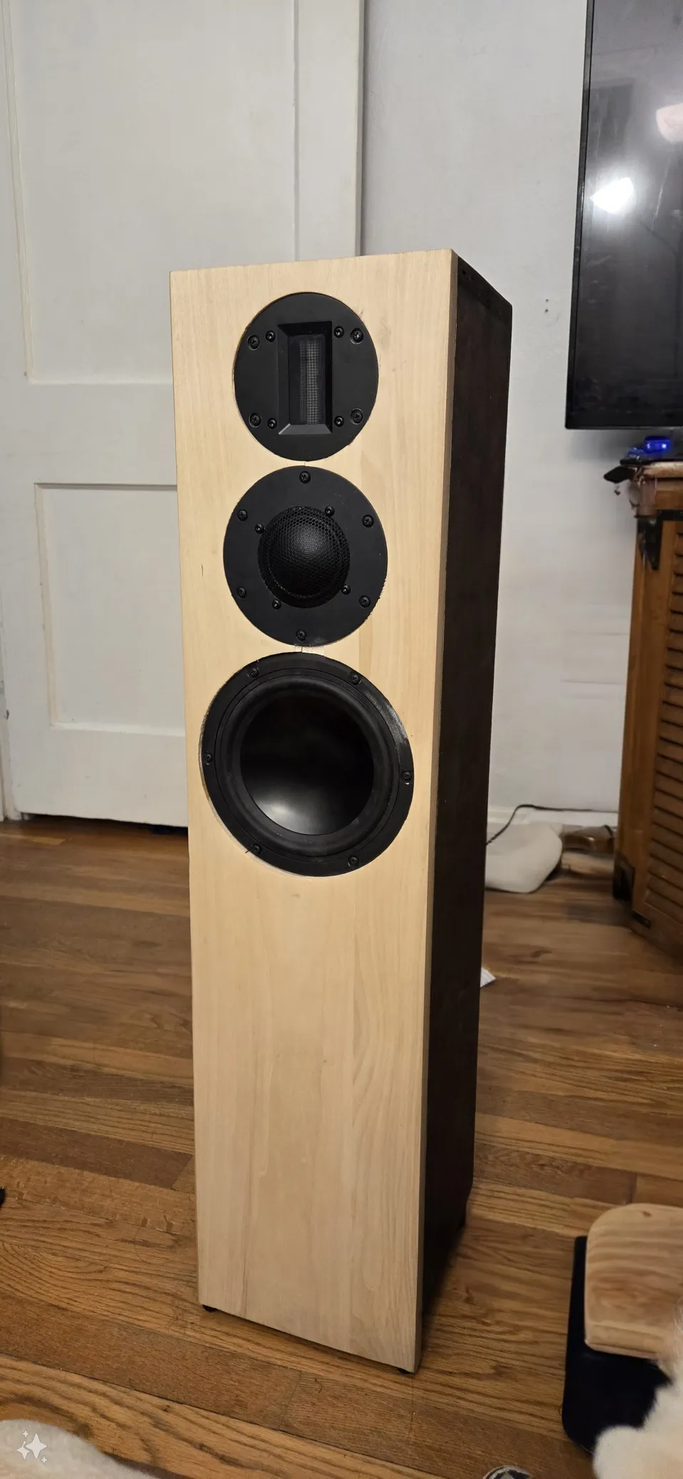
Designed with prototype models available from my time at Dayton Audio around 2023, These are a pair of 3-way Mini-Tower Speakers I like to call the AD-356. Based off the Signature Series SIG180-4, the RS52FN-8 from Dayton Audio, and the RT Series RT1.R-8 from GRS, these Mini-Towers hit my simple goal of needing to dig down fairly deep to an E1 (~40Hz) and stay flat to at least 22kHz. I named them the AD-365 as they are a 3-way design that uses a 6.5" dish, 1" dome midrange, and a flat ribbon tweeter.
BIG NOTE: These are all modeled responses as i no longer have access to the original design files. Though i have attempted to make everything as close to the original as i can remember, there will be variation between modeled and real world performance if you decide to build this.
Driver Selection
While working as the Product Manager for the Parts-Express house brands i would often explore the capabilities of drivers being developed through example designs and experiments, so the primary factor in deciding these drivers was the overlap of the GRS1.R Ribbon tweeter and the SIG180 Woofer. The SIG180 offered fantastic low-end output, with enough upper fidelity for my intended goals in an enclosure that wouldn't be too overbearing, and the RT1.R was a well-priced ribbon package. Originally it was going to be a 2-way to see how far i could push the drivers, but eventually i just wanted a working speaker that i could enjoy, so i added the RS52FN in the mix to keep the ribbon from burning out. You can find out more of the specifics on each driver in the "Component Details" tab.
Enclosure Modeling and Design
Since I had finally decided to use the RS52FN in the design, the only driver that needed enclosure modelling was the SIG180 so I entered the T/S parameters into VituixCAD (Sorry WinISD, i'm a sucker for extensive toolsets) and ended up with something that would be a good compromise considering some real-world limitations. This is the 6-pack view of the enclosure (enclosure design file included in the snapshot)
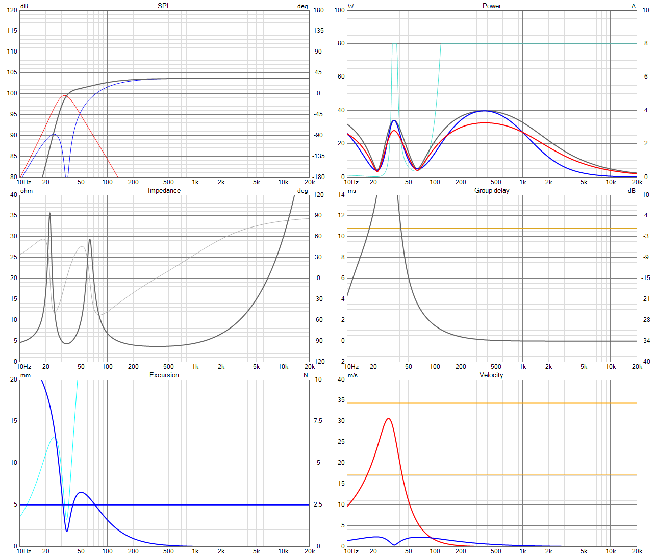
Looking at the Data Entry section, Qa and Ql are defined to reflect an enclosure with lined walls and minor leaks, and the signal power is set at 40w (Half of the rated power, but 10W over the limit set by the RT1.R 30W power handling). A single 4" vent with dual flared ends keeps vent noise to a minimum while extending the low-frequency output to meet my intended goal (or close enough...).
At this power level, there is clearly over-excursion around 60Hz that could cause problems, but i figured that i wouldn't necessarily be hitting these levels consistently enough during normal listening. 103dB SPL is good enough for my living room sessions, and is a fair performance considering the VD of a 6.5" Driver. Accepting these compromises, i moved on to the Auxiliary window in VituixCAD to get some rough dimensions based on the target volume and ran into some resonance issues to watch for.
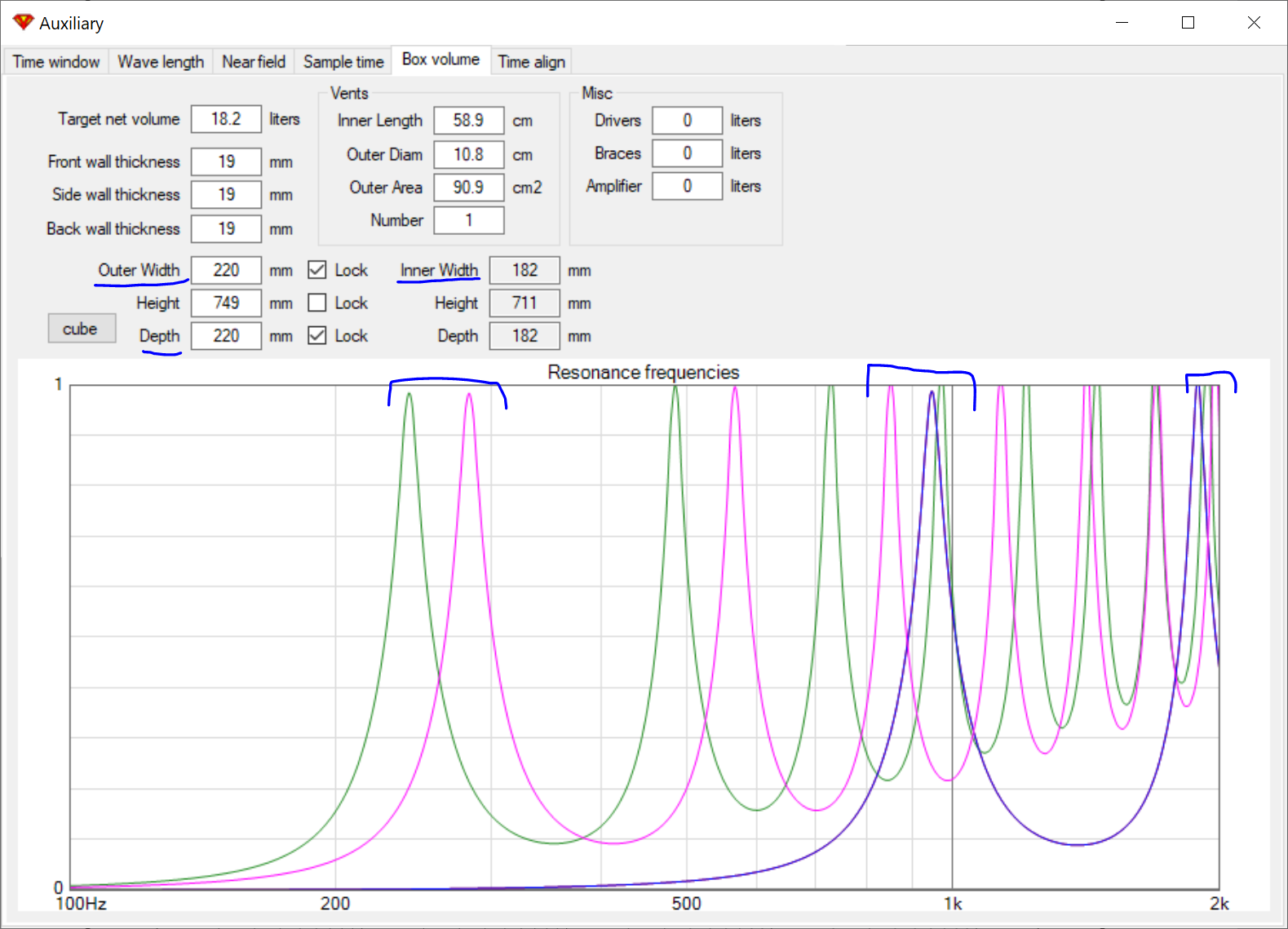
This neat little tool will carry over the target volume and the vent information from the enclosure modelling window and lets you rough in some enclosure dimensions and the relevant resonances for those lengths. I wanted the width of the cabinet to contain the SIG180 without leaving much space on the sides, and the depth to be the same as the width. The SIG180 has a diameter of
180mm, so eyeballing with a measuring tape i ended up with these dimensions (220mm x 749mm x 220mm). After reviewing the resonance frequencies, i noticed there were a few modes that were close enough to interact with each other, particularly around 200Hz, and the first port resonance at around 1kHz (close enough to some higher order modes of the cabinet).
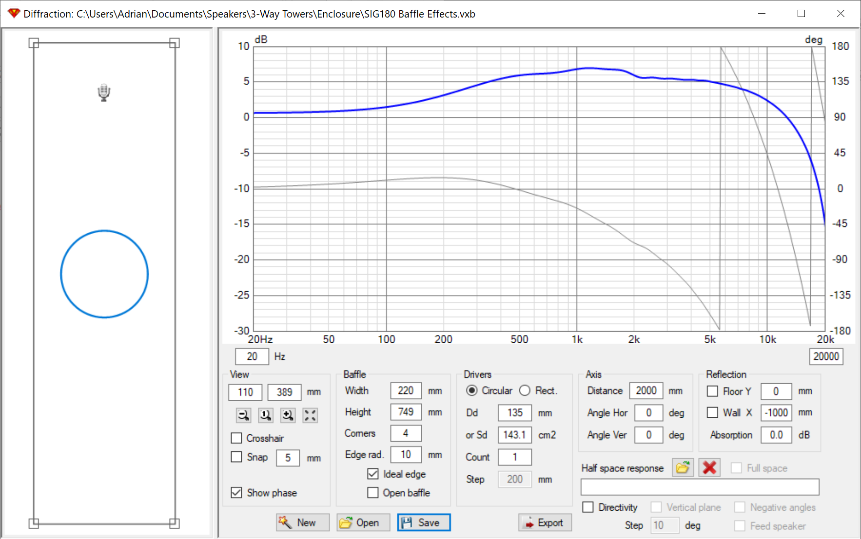
I set the listening position to the height of the tweeter and 2M in distance, added the baffle dimensions, and placed the SIG180 in a position determined by subtracting the diameter of the RT1.R, the RS52FN, 20mm from the top, with 5mm between each driver, AND the radius of the SIG180.
X mm = 749mm - (30mm + 130mm + 110mm + 90mm)
Looking at the transfer function, i decide that a good upper limit for the SIG180 is around 500-800Hz (which avoids the first vent resonance and sits within the acceptable frequency range of the RS52FN) as it keeps BSC for the woofer at an acceptable 6dB shelf.
Drivers
Bar = the band each driver plays, on a 20 Hz to 20 kHz axis
| Band | Driver | Qty | Range | Air volume |
202002k20k
|
|---|---|---|---|---|---|
| LF | Dayton Audio SIG180-4 | 1 | 40 Hz – 600 Hz | 0.64 L | |
| MF | Dayton Audio RS52FN-8 | 1 | 600 Hz – 4.5 kHz | - |
LF · Dayton Audio SIG180-4 1 × · 0.64 L
Since I'm limited by the first vent resonance at 1kHz and the baffle effects leveling off around 800Hz, i don't have to worry too much about break-up in that range. Additionally, once the low-pass filter and BSC are in place, the drop off around 3k will push those 10kHz peaks from the aluminum material below audibility.
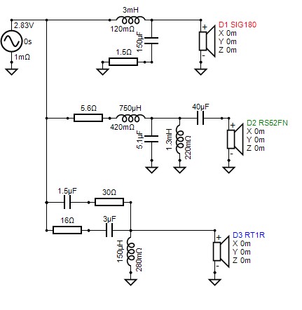
You can get a pretty tight 3rd order LR acoustic slope on this fairly easily. If you were a little more lenient on your requirements, it would use even less components for a 2nd order slope, and the upper resonances will still be pushed down far enough.
MF · Dayton Audio RS52FN-8 1 ×
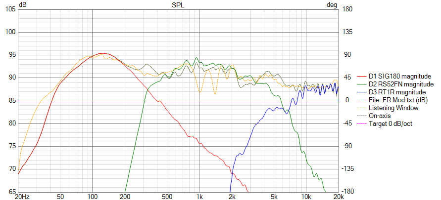
I chose the RS52FN to bridge the gap between the SIG180s 3kHz roll off and the 2kHz corner frequency of the RT1R. The required cutoff frequency to avoid excessive distortion from the ribbon would've placed it above 4.5kHz which is square in breakup territory of the SIG180, leaving a null in the response which would've been exacerbated with the required filtering.
With these constraints in place, the decision was between the Fabric and the Aluminum versions of the dome midrange from Dayton Audio. Looking at the responses between the two I decided to use the Fabric model for 3 main reasons.
The sensitivity of the FN is closer to the SIG180 than the AN making level matching simpler.
The dispersion characteristics of the FN were more favorable in the upper frequency of the passband
The AN midrange exhibits intense ringing above 10kHz due to the aluminum material where the FN does not, meaning i can omit a tank centered around that frequency and minimize component count.
Points Of Interest
Something interesting regarding the RS52FN and the baffle effects overlaps. If you remember the diffraction response from the modeling, there is a peak in step centered around 1kHz. When we look at the manufacturers response of the RS52FN, there is a 3dB dip around 1kHz which means any BSC in regards to the midrange is already offset by 3dB.
Parts list
From the designer's bill of materials
No parts list yet.
What you download
Free with an accountEnclosure files
| Dayton Audio SIG180-4 Bass Reflex Confirmed Measurements.vxe | VXE file | 3 KB |
| Dayton Audio SIG180-4 Bass Reflex.vxe | VXE file | 3 KB |
| RS52FN Baffle Effects.vxb | VXB file | 952 B |
| Dayton Audio SIG180-4 Impedance.txt | Text | 18 KB |
| SIG180 Baffle Effects.vxb | VXB file | 1 KB |
Crossover / electronics files
| Built Crossover.vxp | VXP file | 33 KB |
| Modeled Crossover.vxp | VXP file | 33 KB |
Response previews
| CE RS52FN.frd | FRD frequency response | 15 KB |
| CE RT1R.frd | FRD frequency response | 15 KB |
| CE SIG180.frd | FRD frequency response | 15 KB |
LF Dayton Audio SIG180-4: frequency response files
| SIG180 Modeled.frd | FRD frequency response | 15 KB |
LF Dayton Audio SIG180-4: impedance files
| SIG180-4_DATS.zma | ZMA impedance | 11 KB |
MF Dayton Audio RS52FN-8: frequency response files
| RS52FN Baffle Effects Full-space.txt | Text | 18 KB |
MF Dayton Audio RS52FN-8: impedance files
| RS52FN-8.zma | ZMA impedance | 11 KB |
Versions
Log in to download this design's files. Every version comes as one ZIP, with the build guide PDF made for you.
Reviews
No reviews yet. Be the first to review!
You need to be logged in to write a review.
Log in to write a review